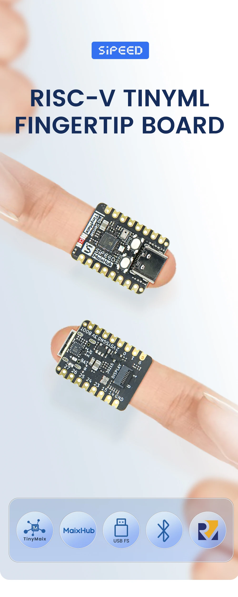
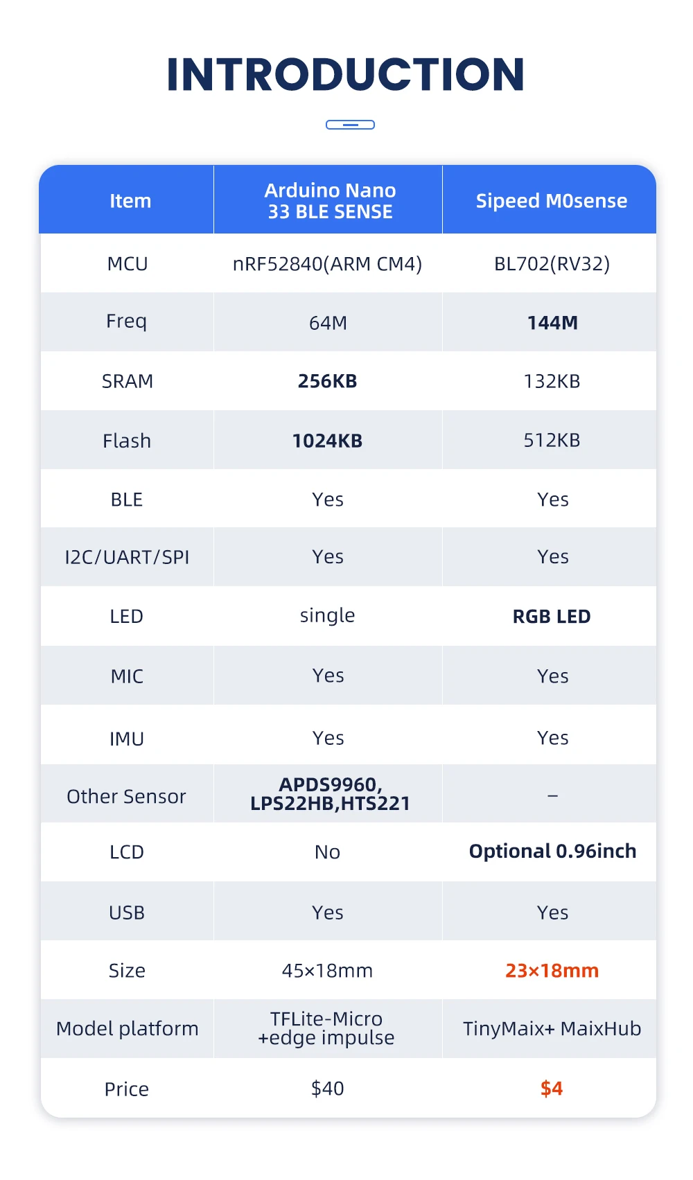
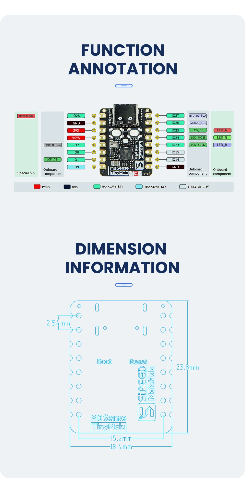
Sipeed M0sense is an AIOT development board based on BL702 of Bouffalo Lab. it's RISC-V architecture, supports low-energy bluetooth. There is a 8Pins FPC connector for connecting LCD screen, 1 microphone, 1 RGB LED and a six-axis sensor chip are on this board.One USB 2.0 FS routes to Type-C interface.
Chip BL702 RISC-V 144MHz
Bluetooth 5.0/ BLE
Onboard screen interface (Optional 0.68 inch 80x160 solution screen)
Onboard 1 analog microphone、1 LED、1 IMU
Route USB 2.0 FS to USB Type-C port
M0sense BL702 RISC-V Board x1
or
M0sense BL702 RISC-V Board with LCD Display x1
AIoT
M0sense |
|
CHIP: BL702 |
|
32 bits RISC-V with FPU (Max Freq 144MHz) |
|
132KB RAM,192KB ROM, 512KB Flash |
|
· Two 32-bit timer |
|
Wireless: |
|
USB 2.0 FS route to USB Type-C to burn firmware |
|
Onboard components |
|
Screen interface (Optional 0.68 inch 80x160 solution screen) |
|
One analog microphone |
|
One RGB LED |
|
One six-axis IMU(QMI8658A) |
|
Ceramic antenna |
|
Others |
|
3D file model: Click me |
|
External TYPE-C PORT power supply requirements: |
|
Temperature rise: <30K |
|
Operating temperature:-10℃ ~ 65℃ |
Comparison
Item |
Arduino Nano 33 BLE SENSE |
Sipeed M0sense |
MCU |
nRF52840 (Cortex M4) |
BL702 (RV32) |
Freq |
64MHz |
144MHz |
SRAM |
256KB |
132KB |
Bluetooth |
Yes |
Yes |
IIC/UART/SPI |
Yes |
Yes |
LED |
Single |
RGB Three color |
MIC |
Yes |
Yes |
IMU |
Yes |
Yes |
Other sensors |
APDS9960,LPS22HB,HTS221 |
|
LCD |
|
Optional 0.68 inch 80x160 solution screen |
USB |
Yes |
Yes |
Dimension |
45mm x 18mm |
23mm x 18mm |
Model platform |
TFLite-Micro + edge impulse |
TinyMaix + MaixHub |
Software
M0sense |
|
OS |
FreeRTOS |
Development |
· C SDK |
Burn Firmware |
· USB virtual uart |
AI Framework |
TinyMaix Framework |
AI model |
· Download from MaixHub. |
Examples |
·https://github.com/sipeed |
Noted:
Item |
Noted: |
Electrostatic protection |
Avoid static electricity hitting the PCBA. Release the static electricity of hand before touching the PCBA |
Operating voltage |
The operating voltage of each GPIO has been marked in the schematic. Please do not allow the actual operating voltage of the GPIO to exceed the rated value, otherwise the PCBA will be permanently damaged |
FPC Connector |
When connecting the FPC cable, make sure that row is completely inserted into the row without bias |
Plug and Remove |
Power off completely before plugging or removing it |
Avoid short circuit |
During the power-on, avoid any liquid or metal touching PCBA components, otherwise the PCBA will be damaged even burn |